
Milepost
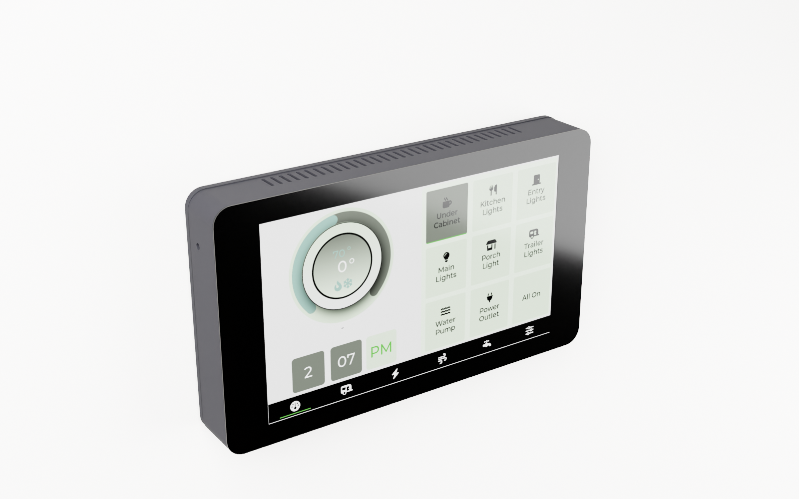
A 7-inch touchscreen control panel that mounts flush to any wall. Every switch, sensor, and system in your rig, right where you need it, with or without a network in sight.
What's Inside / Display
The Wall-Mount Display
A purpose-built touchscreen that sits on the TrailCurrent CAN bus and shows you everything: power state, sensor readings, GPS position, system health. Touch to control. No phone required.
Built around the Waveshare ESP32-S3-LCD-7B, a single board that combines an ESP32-S3 processor, a 7-inch 1024×600 IPS capacitive touch panel, WiFi, and a USB-C port for flashing into one unit. The 3D printed enclosure slides onto a wall-mounted backing plate using 3D printed tabs and slots, no screws to the panel face.
At a Glance
Everything on one board, mounted in two pieces of printed plastic.
Display
7-inch IPS LCD at 1024×600 with a projected-capacitive touch overlay. Wide viewing angles, glare-resistant surface, and enough brightness to read in daylight. The entire panel is integrated on the Waveshare board, so there is no ribbon cable to pinch and no backlight board to seat.
Compute
Waveshare ESP32-S3-LCD-7B. Dual-core Xtensa LX7, 16 MB flash, 8 MB PSRAM, integrated WiFi and Bluetooth, USB-C for first-time flashing. Dual OTA partitions mean updates land on the inactive half and the bootloader swaps them on reboot, so a bad update never bricks the panel.
Wall Mount System
Two-piece slide-on design. A wall plate screws to any flat surface; the screen backing slides straight down, tabs riding in matching slots, until it locks flush. No fasteners visible on the face of the panel. Pull up to remove. The JST SM connector carries CAN H and CAN L to the wall plate. Power wires from the screen solder directly to the buck converter.
Bill of Materials
Everything you need to build one Milepost, top to bottom.
| Qty | Part | Description | Source |
|---|---|---|---|
| 1 | Waveshare ESP32-S3-LCD-7B | All-in-one ESP32-S3 board with an integrated 7-inch 1024×600 IPS capacitive touch display, 16 MB flash, 8 MB PSRAM, WiFi, Bluetooth, and USB-C. No separate display module or cable to manage. | Waveshare |
| 1 | Screen Backing | 3D printed. Houses the Waveshare board, forms the slide-on tabs that ride in the wall plate slots, and exposes the display face. 193×111×38 mm overall. ABS or ASA recommended. | 3D printed, Makerworld or STL below |
| 1 | Wall Mounting Plate | 3D printed. Screws flat against any wall surface. Printed slots accept the screen backing tabs for a tool-free, no-fastener installation. ABS or ASA recommended. | 3D printed, Makerworld or STL below |
| 4 | M3 Standoffs | Brass M–F standoffs that space the Waveshare board off the backing plate interior and hold it in registration with the display cutout. Included with the Waveshare screen. | Included with screen |
| 4 | M5×12 mm Machine Screws | Mount the wall plate to the wall surface at the four corner bosses. | Hardware store |
| 1 | JST SM 4-pin Connector | JST SM male/female pair carrying CAN H and CAN L. The screen's power wires solder to the buck converter; the screen's CAN connector solders to the two CAN wires of this JST SM pair. | BTF-LIGHTING |
Technical Drawings
Orthographic views of the full assembly, straight out of the FreeCAD model.
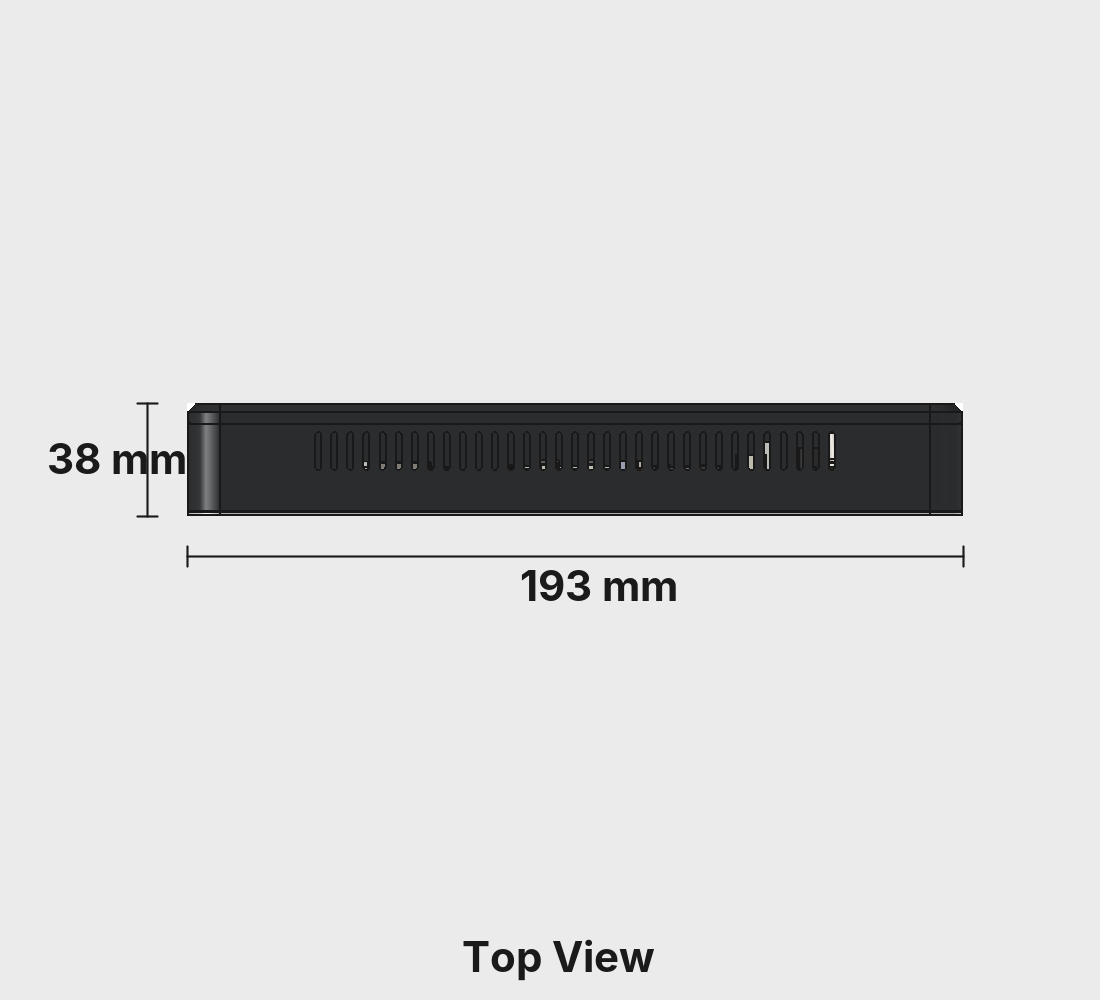
Top View
The mounting tab slots visible along the top edge, ventilation profile, and overall 193 mm width.
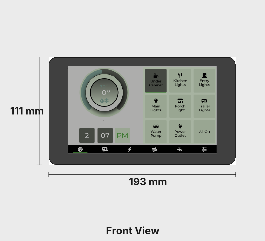
Front View
Display face with the 7-inch touch panel. 193×111 mm overall panel footprint.
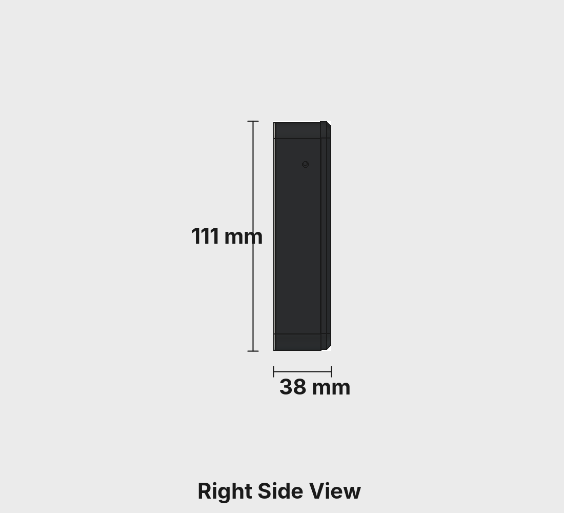
Right Side
The slide-on tab profile that rides in the wall plate slots. 38 mm depth from wall surface to display face.
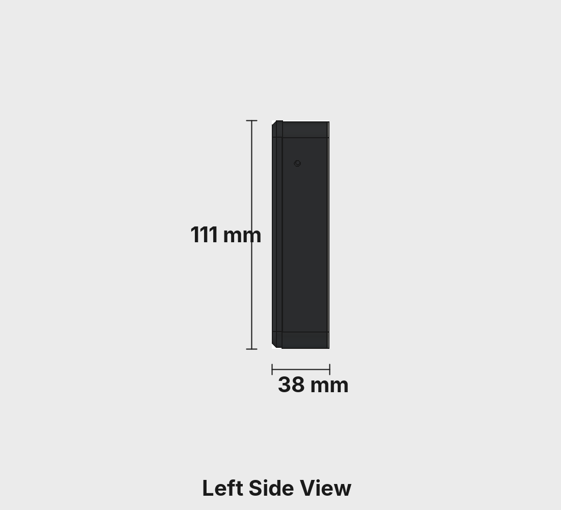
Left Side
Mirror of the right. The enclosure closes off all ports once assembled, so firmware is flashed on the bench before installation.
Overall dimensions: 193 × 111 × 38 mm. Source CAD lives in the CAD folder of the Milepost repo.
3D Printed Parts
Two pieces, ABS. The wall plate installs once; the screen backing clicks in and out without tools.
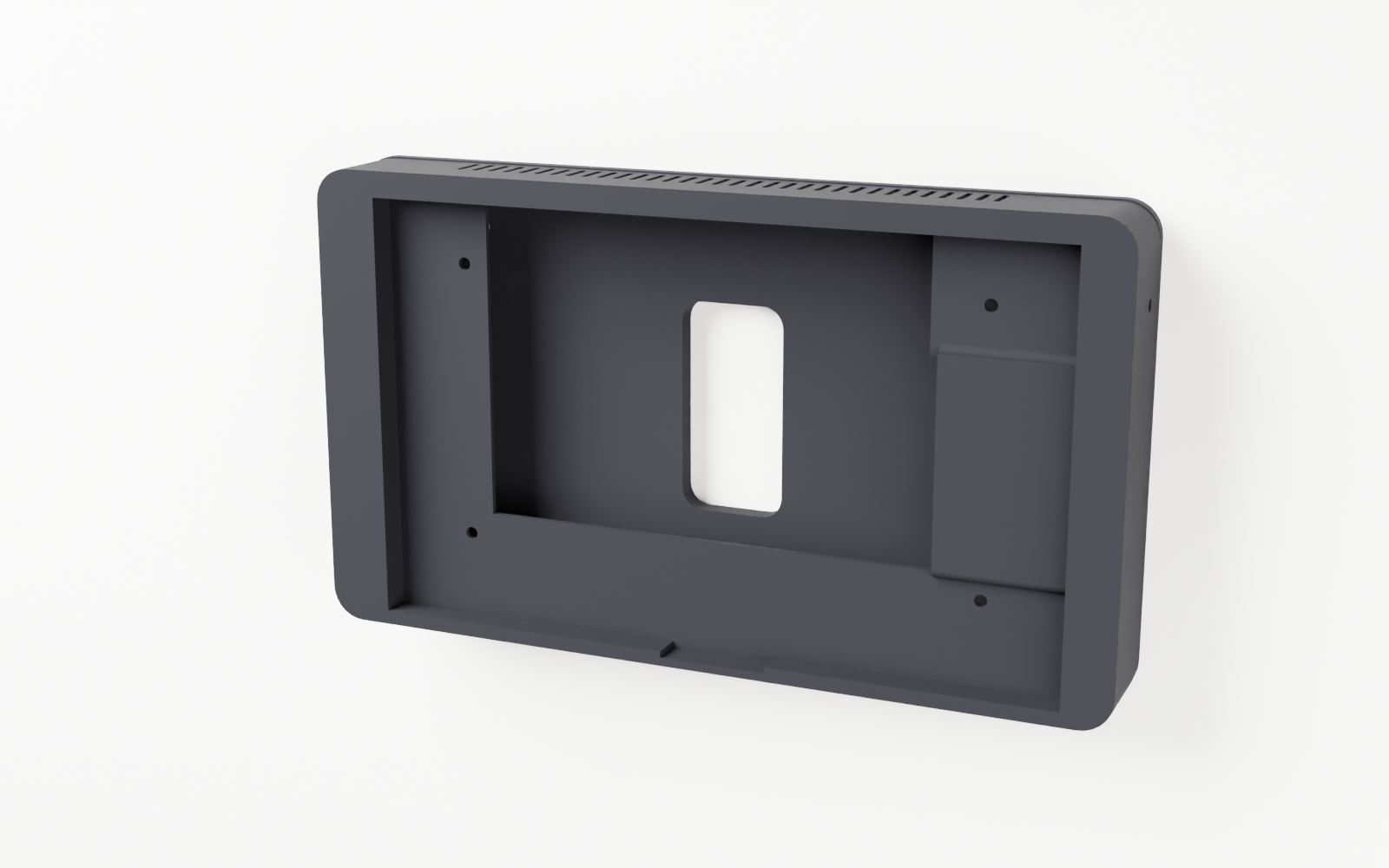
Screen Backing
The main body. A deep pocket behind the display face holds the Waveshare board on four brass standoffs, flush to the bezel. Four interlocking tabs on the rear face slide into the wall plate channels and lock the assembly against the wall with no exposed fasteners on the display side.
- Dimensions: 193 × 111 × 38 mm
- Material: ABS (or ASA)
- Nozzle: 0.4 mm
- Layer height: 0.2 mm
- Walls: 4 perimeters
- Infill: 20% (gyroid)
- Supports: Tree (auto), on build plate only
- Nozzle temp: 270 °C (260 °C first layer)
- Bed temp: 90 °C
- File:
BodyMilepostScreenBacking.stl
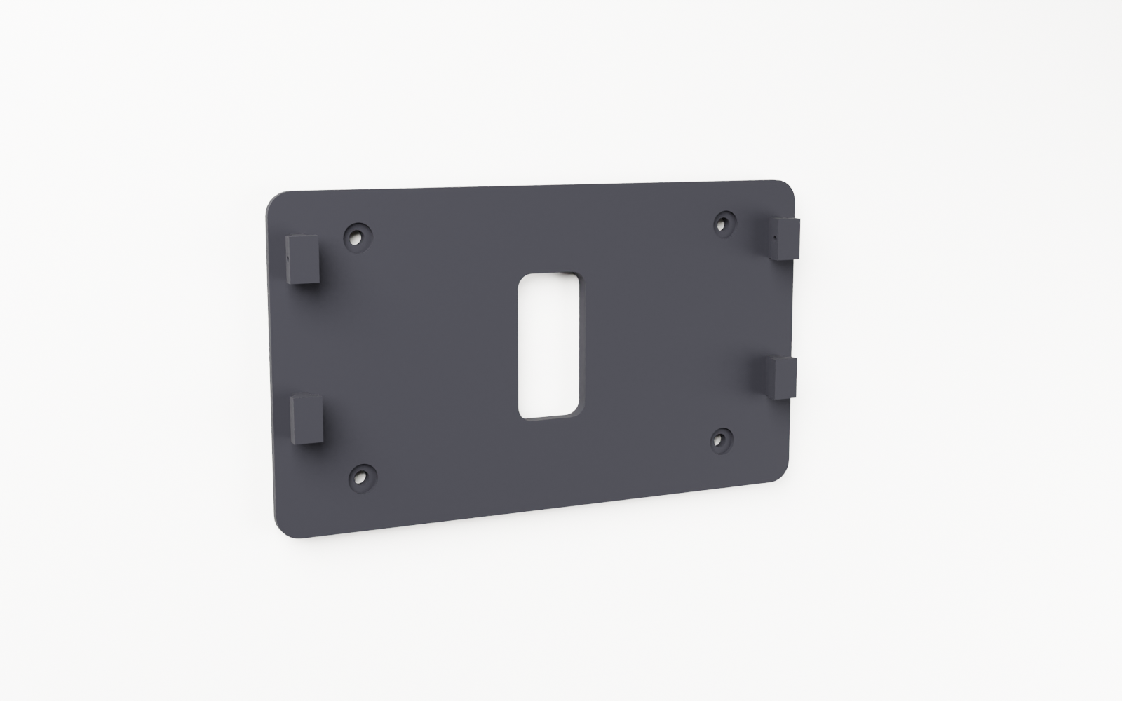
Wall Mounting Plate
A slim plate that screws to any flat surface using four M5 fasteners at the corners. Four 3D printed channel slots accept the screen backing tabs from the top and guide them straight down to the seated position. The JST SM connector lives on the wall plate so the CAN bus wiring stays permanently installed, separate from the removable screen unit.
- Dimensions: 193 × 111 × 12 mm
- Material: ABS (or ASA)
- Nozzle: 0.4 mm
- Layer height: 0.2 mm
- Walls: 4 perimeters
- Infill: 40% (grid)
- Orientation: Upright on edge
- Nozzle temp: 270 °C (260 °C first layer)
- Bed temp: 90 °C
- File:
BodyWallMountingPlate.stl
Hardware
One off-the-shelf board does everything. No custom PCB, no soldering.
MCU and Display
The Waveshare ESP32-S3-LCD-7B integrates everything on one board. Dual-core Xtensa LX7 up to 240 MHz, 16 MB flash split into dual OTA partitions, 8 MB PSRAM for frame buffers, and the 7-inch IPS panel all ship together. Firmware is flashed on the bench via USB-C before the board goes into the enclosure, using the TrailCurrent Flasher. All subsequent updates land over the air. The enclosure closes off all ports once installed.
Power
12 V comes in from the harness and feeds a buck converter that steps it down to 5 V for the Waveshare board. The screen's power wires solder to the buck converter output.
CAN Interface
CAN H and CAN L come in through the same JST SM connector as power. The ESP32-S3 TWAI peripheral talks to an on-board CAN transceiver at 500 kbps. Milepost listens to the bus for sensor readings, system states, and GPS data from other modules, and sends control commands back.
Slide-On Mounting
The wall plate stays permanently mounted. Four interlocking tabs on the screen backing drop into slots on the wall plate and ride downward until the unit is fully seated. A small retention feature locks it in place. To remove, press the release and lift. The JST SM connector on the wall plate side connects CAN H and CAN L when the unit is seated.
Assembly
The wall plate goes up once. After that, the screen snaps in and out in seconds.
-
1
Print both parts
Open
TrailCurrentMilepostCase.3mfin Bambu Studio or Orca, or grab it directly from Makerworld. The screen backing prints flat; the wall plate prints upright on edge. ABS, 0.2 mm layers, 4 walls. -
2
Flash the firmware
On the bench, plug the Waveshare board into USB-C and flash the Milepost firmware using the TrailCurrent Flasher. Every subsequent update arrives over the air once the board is on the CAN bus.
-
3
Seat the board in the backing plate
Peel the adhesive liner from the back of the Waveshare screen. Place the board into the backing plate display-face-forward, aligned to the cutout. Thread the four brass standoffs through the board's mounting holes into the backing plate to lock it in place.
-
4
Wire and mount the wall plate
Solder the screen's power wires to the buck converter output. Solder the screen's CAN connector to the two CAN H / CAN L wires of the JST SM pair. Connect 12 V and GND from your harness to the buck converter input and the JST SM male side. Screw the wall plate flat against the wall at the four corner bosses using M5×12 mm fasteners.
-
5
Slide on the screen
Plug the JST SM female connector on the screen backing into the male connector on the wall plate wiring. Hold the screen backing above the wall plate with tabs aligned to slots and slide straight down until it seats flush.
-
6
Power on
Apply 12 V to the CAN bus harness. Milepost boots, joins the bus, and begins displaying live data within a few seconds. No configuration required if Headwaters is already on the network.
CAN Protocol
Milepost listens to the full bus and sends control commands back. No CAN ID conflicts with the sensor modules.
Bus Listener
Subscribes to all standard TrailCurrent CAN IDs: power state from Torrent, GPS from Bearing, air quality from Borealis, leveling from Plateau, tank levels, solar data. Whatever is on the bus shows up on screen.
Control Output
Touch events translate to CAN commands targeting Torrent (power switching), Headwaters automations, and individual module control frames. One tap on the display sends the same CAN frame that a cloud command or mobile app would send.
OTA Over CAN
Broadcast CAN ID 0x00 with Milepost's last
three MAC bytes and it joins WiFi, serves a firmware upload
endpoint, and writes the new image to the inactive OTA slot.
A clean flash swaps on reboot; anything less and it stays
on the known-good side.
Build Your Own Milepost
CAD, firmware, and the CAN protocol spec are all in the repository. One board, two printed parts, and your rig has a proper control panel.