
Reservoir
Fresh, grey, and black water levels for the whole rig, straight onto the CAN bus. No floats to clean, no probes to corrode. Just contactless sensors and a quiet little box that watches your tanks so you don't have to.
What's Inside / Module
The Water Tank Monitor
Reservoir reads up to twelve contactless level sensors, four each on your fresh, grey, and black water tanks, and publishes the fill level of each tank as a clean 0–100% value once a second on the TrailCurrent CAN bus. Any other module on the bus can pick it up.
Built around the Waveshare ESP32-S3 RS485 CAN board running ESP-IDF with FreeRTOS. Sensors hang off a twenty-pin IDC ribbon broken out into three Deutsch DTM 12-pin connectors, one cable per tank. A fourth Deutsch DTM 4-pin carries power and the CAN H/CAN L pair. The whole thing lives in a two-piece 3D printed case you can tuck into the utility bay.

At a Glance
What's inside the case and what comes out of the connectors.
Compute
Waveshare ESP32-S3 RS485 CAN board. Dual–core Xtensa LX7 running pure C on ESP-IDF 5.5, with an on-board CAN transceiver and USB-C for flashing. 8 MB flash with dual OTA partitions, so updates are safe and roll back on their own if something goes wrong.
Sensor Inputs
Twelve GPIO pull-downs, one per sensor. Four sensors per tank at the 25%, 50%, 75%, and 100% marks, active–HIGH when water reaches them. The firmware reports the highest triggered level per tank, so a tank with no sensors wired reads a clean 0%.
Vehicle Network
500 kbps CAN bus through the Waveshare board's on-board
NXP TJA1051T transceiver and the ESP32-S3 TWAI peripheral,
broken out to a Deutsch DTM 4-pin connector. Tank levels
publish once a second at CAN ID 0x3E as
three bytes: fresh, grey, black.
Bill of Materials
Everything you need to build one Reservoir, top to bottom.
Some source links are affiliate links (Amazon, Waveshare). They cost you nothing extra and send a small cut back to the project.
| Qty | Part | Description | Source |
|---|---|---|---|
| 1 | Waveshare ESP32-S3 RS485 CAN Board | ESP32-S3 dev board with on-board CAN transceiver (NXP TJA1051T), RS485 driver, USB-C, and a 7–36 V wide-input power rail. Off-the-shelf. | Waveshare |
| 12 | DFRobot Gravity Non-contact Liquid Level Sensor | Non-invasive, non-contact capacitive level sensor that sticks to the outside of the tank wall. 5 V input, 3.3 V logic-compatible output, active–HIGH when water is present. Four sensors per tank, three tanks. | DFRobot |
| 1 | 20-pin IDC Ribbon Cable | Ribbon from the Waveshare board's GPIO header out to the three sensor connectors. Red stripe aligns with pin 1 at the 3.3 V/5 V end. | Generic |
| 3 | Deutsch DTM04-12PA Connector | 12-pin receptacles, one per tank. Four sensor signals plus shared power and ground on each cable. Sealed and latching for the utility bay. | TE Connectivity |
| 1 | Deutsch DTM04-4P Connector | 4-pin receptacle carrying 12 V power and the CAN H / CAN L pair. The TrailCurrent standard for vehicle bus interconnects. | Amazon |
| 1 | Case Bottom | 3D printed. 170 × 170 × 27 mm, with integrated standoffs for the Waveshare board and openings on one side for the three DTM12 sensor connectors and the DTM4 CAN connector. ABS or ASA recommended. | 3D printed (STL below) |
| 1 | Case Cover | 3D printed. 145 × 170 × 7.5 mm. Embossed TrailCurrent logo and Fresh / Grey / Black sensor connector labels on the top face. Seats inside the mounting tabs of the bottom half. ABS or ASA recommended. | 3D printed (STL below) |
| 12 | M3 × 8 mm Machine Screws (lower mount) | ISO 7047 pan-head. Go in from the bottom of the case: head seats in a countersunk pocket on the outside of the case floor, the shaft passes up through the floor and the lower sensor board, and threads into the bottom of an M3 standoff. Two per lower sensor board, six boards, twelve screws. Stainless or zinc-plated. | Hardware store |
| 12 | M3 × 8 mm Brass Standoffs (5.5 mm hex) | Female-female PCB spacers with M3 threads on both ends and a 5.5 mm hex body. Sit between the lower and upper layers of DFRobot sensor boards, turning one plane of sensors into two stacked rows of six. The lower-mount screws thread into the bottom of each standoff and the upper-mount screws thread into the top. | Hardware store |
| 12 | M3 × 8 mm Machine Screws (upper mount) | ISO 7047 pan-head. Go in from the top: pass down through the upper sensor board and thread into the top of the M3 standoffs underneath, locking the upper board to the stack. Two per upper board, six boards, twelve screws. Stainless or zinc-plated. | Hardware store |
| 4 | M2.5 × 6 mm Machine Screws (case cover) | Secure the cover to the case bottom at the four corners. Stainless or zinc-plated steel. | Hardware store |
Technical Drawings
Orthographic views of the full assembly, straight out of the FreeCAD model.
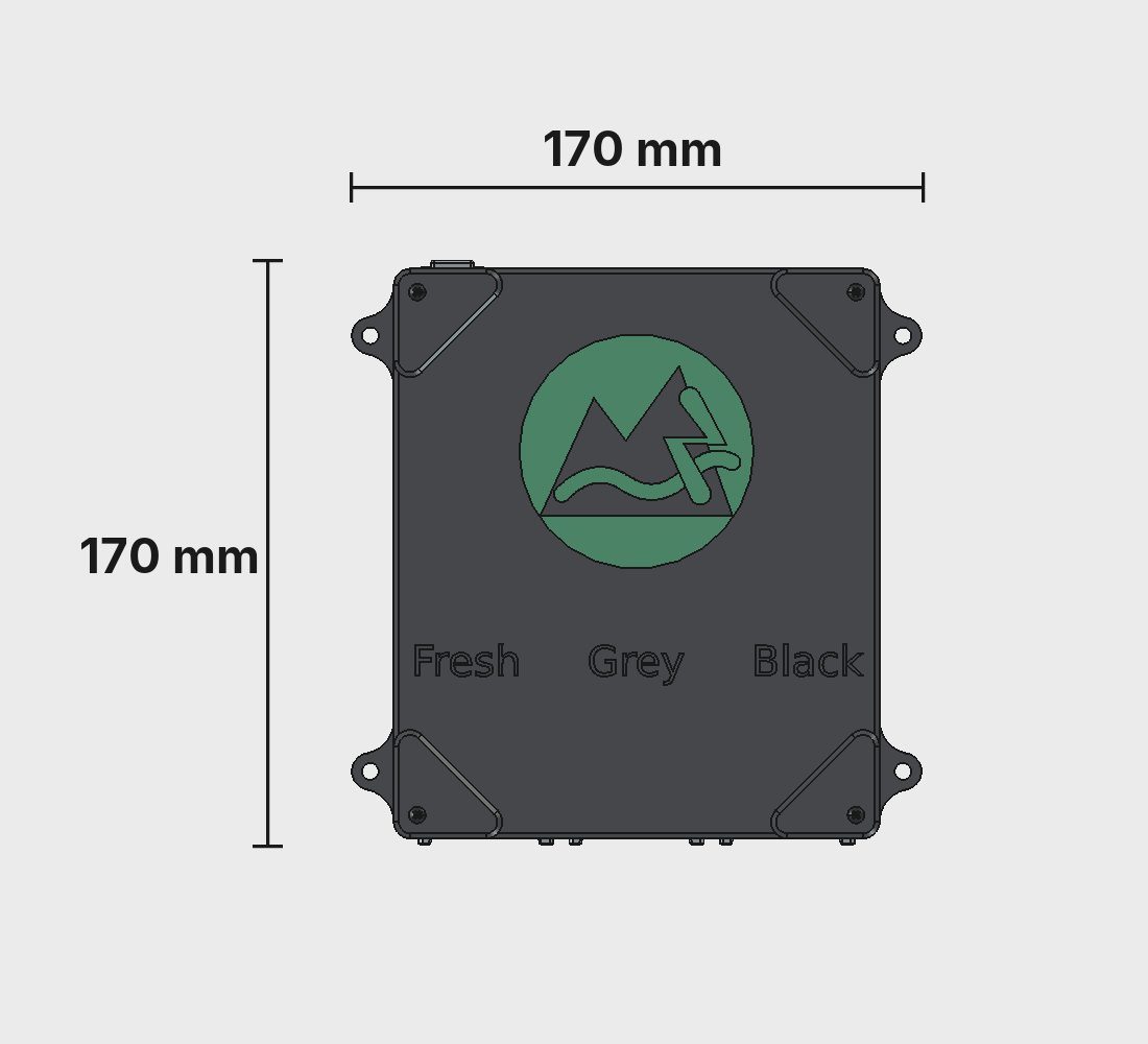
Top View
Embossed TrailCurrent logo on the cover with Fresh, Grey, and Black labels lined up over the three sensor connectors. Four mounting tabs at the corners.
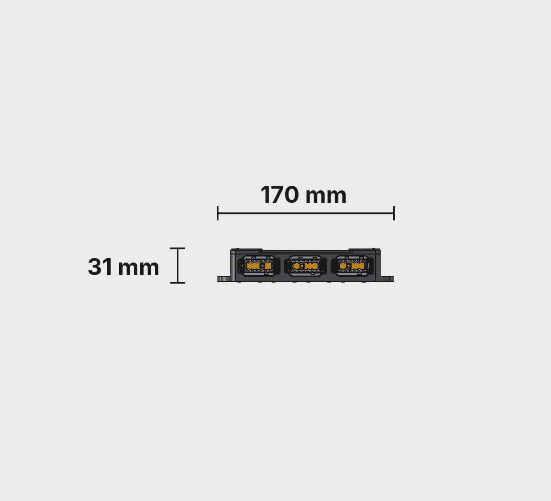
Connector Side
Three Deutsch DTM04-12PA sensor connectors for the fresh, grey, and black tanks, plus a DTM04-4P for power and CAN. One cable per tank, one cable for the bus.

Right Side
Low profile from the side. The case is 31 mm thin, so it tucks under a cabinet or inside a utility bay without eating any real space.
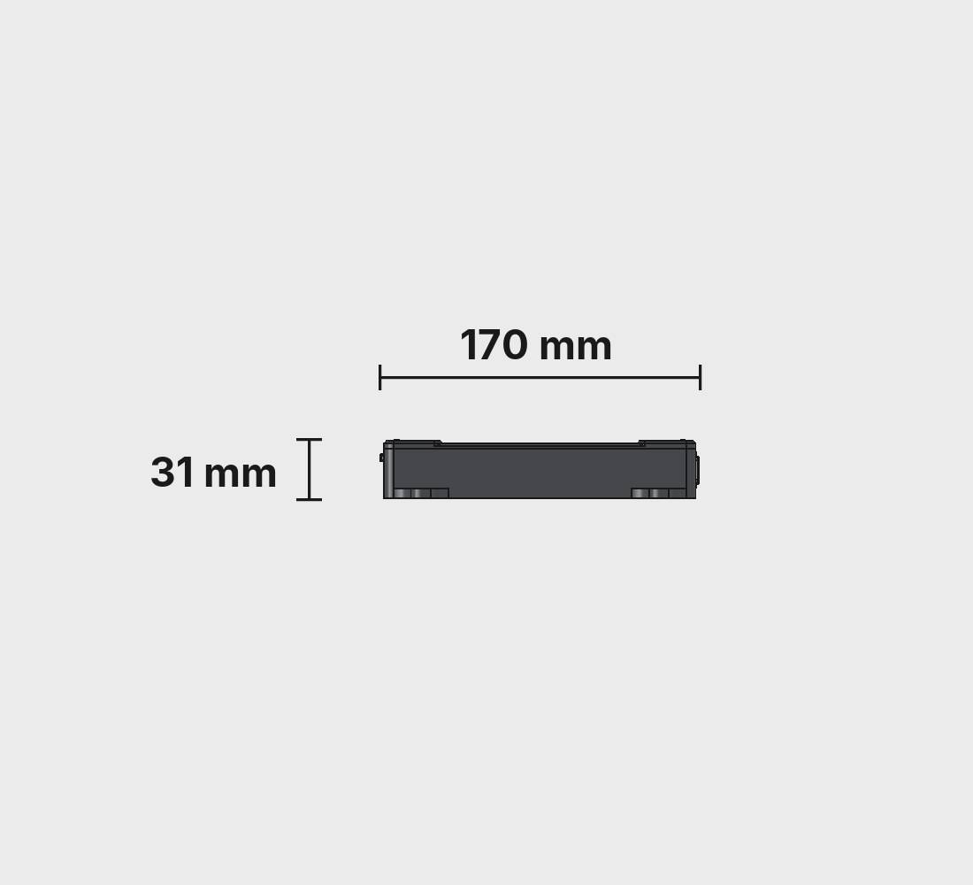
Left Side
Mirror of the right side. The mounting tabs at each corner ride above the case floor so screws can reach from above without fouling the cover.
Overall dimensions: 170 × 170 × 31 mm. Source CAD lives in the CAD folder of the Reservoir repo.
3D Printed Parts
Two pieces, ABS. A ready-to-print project lives on Makerworld, and the raw .3mf and STL files are in the CAD folder of the repo.

Case Bottom
The main body. Integrated standoffs hold the Waveshare ESP32-S3 board, and the short end frames the three DTM12 sensor connectors and the DTM4 CAN connector. Four mounting tabs at the corners let you bolt it wherever it needs to live.
- Dimensions: 170 × 170 × 27 mm
- Material: ABS (or ASA)
- Nozzle: 0.4 mm
- Layer height: 0.2 mm
- Walls: 6 perimeters
- Infill: 100% (zig–zag)
- Supports: Tree (auto), 30° threshold
- Nozzle temp: 270 °C (260 °C first layer)
- Bed temp: 90 °C
- File:
BodyReservoirCaseBottom.stl

Case Cover
The lid. A flat plate with the TrailCurrent logo embossed on the top face and four clearance holes for the cover screws. Seats inside the four mounting tabs of the bottom half. Print with the logo face up for the cleanest finish.
- Dimensions: 145 × 170 × 7.5 mm
- Material: ABS (or ASA)
- Nozzle: 0.4 mm
- Layer height: 0.2 mm
- Walls: 6 perimeters
- Infill: 100% (zig–zag)
- Supports: None (prints flat, logo face up)
- Nozzle temp: 270 °C (260 °C first layer)
- Bed temp: 90 °C
- File:
BodyRservoirCaseCover.stl
Hardware
One off-the-shelf board, a ribbon cable, and twelve sensors on the outside of your tanks. No custom PCB.
MCU Board
Waveshare ESP32-S3 RS485 CAN board. Dual–core Xtensa LX7 with integrated WiFi and Bluetooth, 8 MB flash, USB-C for flashing, and an on-board NXP TJA1051T CAN transceiver. 8 MB flash is split into two OTA partitions so updates land on the inactive half and the bootloader swaps them on reboot.
Power
12 V comes in over the DTM4 connector and lands on the Waveshare board's wide-input regulator (7–36 V range). The 5 V rail feeds the contactless sensors, and the 3.3 V rail runs the ESP32-S3 itself. The CPU clock is pinned at 80 MHz to keep quiescent draw low. This module sits on the bus all the time.
Sensors
Twelve non-contact capacitive level sensors stuck to the outside of the fresh, grey, and black tanks at the 25%, 50%, 75%, and 100% marks. Contactless means nothing in the tank to clean, clog, or corrode. Critical for the grey and black sides where traditional probes get gross fast.
CAN Interface
The board's on-board CAN transceiver connects straight to the ESP32-S3 TWAI peripheral in normal mode with full alert handling. 500 kbps, standard 11-bit identifiers, and automatic bus-off recovery so a module joining or leaving the bus never stalls the rest of the rig.
Assembly
The enclosure goes together fast. Sticking the twelve sensors to your tanks is the part that takes a minute.
-
1
Print the case
Easiest path: open
TrailCurrentReservoir.3mffrom the CAD folder in Bambu Studio (or Orca) and print both plates. ABS, 0.2 mm layers, 100% infill, 6 walls, tree supports on the bottom. If you're slicing from STL, match those settings; the cover prints flat with no supports. -
2
Flash the firmware
On the bench, plug the Waveshare ESP32-S3 RS485 CAN board into USB-C and flash the Reservoir firmware straight from your browser using the TrailCurrent Flasher. After the first flash, all future updates happen over the air through the CAN bus trigger protocol.
-
3
Wire the sensor harnesses
Crimp three DTM12 harnesses, one per tank. Each cable carries 5 V, ground, and the four sensor signals for that tank (25%, 50%, 75%, 100%). Match the pinout in
DOCS/reservoir-ribbon-cable.svg. The ribbon into the Waveshare board uses an IDC connector with the red stripe aligned to pin 1. -
4
Mount the lower sensor board layer
Drop the six lower DFRobot Gravity sensor boards into their pockets on the case floor. From the outside bottom of the case, drive twelve M3 × 8 screws up through the countersunk holes, through each lower board, and thread them into the bottom of a brass M3 standoff on the inside. Two screws and two standoffs per board. Don't crank them down. The boards should sit flat without flex.
-
5
Stack the upper sensor board layer
Set the remaining six DFRobot Gravity sensor boards on top of the standoffs, lining up each board's mounting holes with the standoff tops. Drive twelve M3 × 8 screws from the top down through the upper boards and into the female threads at the top of each standoff. You now have two rows of six sensor boards, one above the other, with the ribbon routing space running down the middle.
-
6
Drop the Waveshare board in
Set the Waveshare ESP32-S3 RS485 CAN board into its pocket beside the sensor stack. Press the three DTM12 receptacles and the DTM4 receptacle into their openings on the short side of the case and tighten their back nuts.
-
7
Close the case
Drop the cover on between the four mounting tabs. Secure with four M2.5 × 6 mm screws at the corners. Snug, not cranked down; the plastic threads are gentle.
-
8
Stick the sensors to your tanks
Clean the outside of each tank with isopropyl where the sensors land. Stick four sensors per tank at the 25%, 50%, 75%, and 100% marks. These are non-contact capacitive sensors that read through the tank wall, so nothing touches your water. Plug each tank's harness into the matching DTM12 receptacle.
-
9
Plug it in
Plug the DTM4 connector into the TrailCurrent bus. Within a second Reservoir is publishing fresh, grey, and black water levels as 0–100% values at CAN ID
0x3E. Headwaters will pick it up and show it on the dashboard automatically.
Sensor Layout
Four sensors per tank, three tanks, one ribbon cable back to the box.
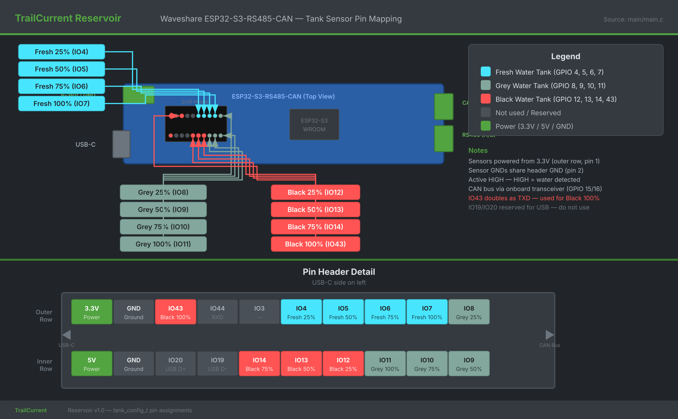
Reading Logic
Water rises from bottom to top, triggering sensors sequentially. Reservoir reports the highest sensor reading HIGH per tank. If a tank isn't physically connected, all its sensors stay LOW and the level reports a clean 0%.
- None triggered → 0%
- 25% only → 25%
- 25% + 50% → 50%
- 25% + 50% + 75% → 75%
- All four → 100%
The firmware polls all twelve sensor GPIOs every 500 ms on the main task. The CAN task runs independently on core 1, so sensor polling never stalls on bus activity and bus errors never stall sensor polling.
CAN Protocol
One outbound message at 1 Hz, plus the standard bus-management IDs every TrailCurrent node speaks.
| ID | Name | DLC | Payload |
|---|---|---|---|
0x3E |
WaterTankLevels | 3 | Byte 0: fresh water fill 0–100%. Byte 1: grey water fill 0–100%. Byte 2: black water fill 0–100%. Transmitted once per second. |
0x04 |
Version Report | 6 | Transmitted once at boot: last three MAC bytes and firmware major / minor / patch. |
0x00 |
OTA Trigger (RX) | 3 | Last three MAC bytes of the target device. If it matches, Reservoir enters OTA mode, joins WiFi, and serves an HTTP upload endpoint. |
0x01 |
WiFi Config (RX) | variable | Chunked SSID / password provisioning stored in NVS. |
0x02 |
Discovery (RX) | 0 | Broadcast trigger for mDNS self-discovery so Headwaters can inventory the module automatically. |
Percentage Protocol
Tank levels go on the bus as 0–100% bytes, not raw sensor states. That keeps the wire format stable if we move from four-step binary sensors to a continuous analog reading later. Only the firmware changes, not the bus or any consumer.
Bus-Off Recovery
The TWAI driver runs in normal mode with full alert handling. Bus-off kicks off automatic recovery, a restart brings the bus back up, and transmissions resume. Nodes can come and go on the bus without requiring a reboot.
OTA Over CAN
Broadcast CAN ID 0x00 with Reservoir's last three
MAC bytes and it joins WiFi, spins up an HTTP server, and
accepts a new firmware image. It writes to the inactive OTA
slot and reboots; if anything fails, it rolls back.
Build Your Own Reservoir
Every file is in the repository: CAD, ESP-IDF firmware, the CAN protocol spec, and the sensor wiring guide. Fork it, build it, make it yours.